About us
FASTPCBA Co.,Ltd
-
 Building 1, Senyang Electronic Technology Park, Guangming High-tech Park, Yutang Street, Guangming District, Shenzhen City.
-
 F:86-13418481618
-
 pcba13@fastpcba.cn
 date:2021-01-04 17:19:39
To generate tangible projects of any degree of complexity, there are four basic requirements:
1. Is a clear plan or strategy.
2. Is the knowledge or expertise necessary to execute the plan.
3. Have the necessary tools or equipment.
4. You need time to integrate the first three.
With these basic elements, almost anything can be achieved or produced. However, the quality of the results usually depends on the specific equipment and its efficiency.
The development of PCBA is a good example of how to realize these four aspects of product generation. The process starts and depends on a well-defined design, which includes specifying all materials, components and their layout, or stacking and PCB layout. By using PCB assembly equipment to place and firmly fix the components, the design embodiment is finally determined. For surface mount components, as well as pick and place, reflow is the most important stage.
First, let us define reflow soldering, and then study how to best design circuit boards to avoid potential reflow-induced failures, which may threaten the successful development of PCBA.
Reflow soldering is a surface mount technology (SMT) process that is used to connect components to the top layer of the PCB. For double panels, the bottom layer is the same. The process involves running the circuit board through an oven and going through a four-stage profile: preheating, soaking, reflow, and cooling. The temperature and time interval of each stage are preset according to the following parameters: circuit board size, number of components, number of layers, type of solder, etc.
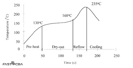
As mentioned above, during assembly, reflow soldering is used to fix the SMD to the circuit board. The reflow phase of the circuit board assembly is a thermodynamic process in which the circuit board goes through four intervals of temperature ranges, as shown in the figure below.

(Infrared reflux curve)
The temperature shown in the above reflow curve is the typical temperature of solder paste most commonly used by PCB contract manufacturers (CM). The peak value of lead-containing solder is about 210-220°C, and the peak value of lead-free solder is about 30°C. It should also be noted that it is ideal that the temperature during the drying or soaking stage is fairly constant. The same is true in the reflow phase, because the temperature should be equal to or higher than the required peak temperature within a fixed preset time. As described below, failure to observe the proper temperature or time interval can cause malfunctions.
Potential failures when soldering SMD:
Although the through-hole soldering process may encounter challenges, these challenges are trivial compared to the possibility of failure caused by reflow. Possible problems range from poor solder joint quality to component and/or circuit board damage. These and other unexpected situations are listed below.
Type of failure caused by reflow:
1. Oxide formation-occurs when oxygen is present during reflow.
2. Solder balls and/or solder balls-may be caused by insufficient heat.
3. Grasp-due to exhaustion of flux.
4. The headrest is in the pillow-it may happen due to too high soaking temperature or too long interval.
5. Component cracking-caused by excessive heating speed.
6. The circuit board warps or breaks-due to the pressure applied after the circuit board weakens during reflow.
The above-mentioned unexpected situation is caused by inaccurate reflow soldering execution; however, there are some design factors that make the circuit board susceptible to these failures. Fortunately, these problems can be avoided, as described below.
Design criteria to prevent failures caused by reflow:
In many cases, failures caused by reflow mean that unusable boards are being manufactured, which can lead to longer turnaround times and increased manufacturing costs. However, these manufacturability surprises can be greatly reduced by adopting a "design by value" approach, including making decisions that help CM assemble circuit boards, as shown below.
How to avoid failure caused by reflow:
1. Balance the copper distribution on the ship.
2. Make sure that the dimensions of the PCB traces connected to the components are similar.
3. Choose high-quality components without leaking reflow temperature.
4. Make sure there is enough space between the boards.
5. Make full use of thermal paste and other heat transfer technologies when necessary.
6. Please follow good design guidelines regarding footprints.
 Building 1, Senyang Electronic Technology Park, Guangming High-tech Park, Yutang Street, Guangming District, Shenzhen City.
 F:86-13418481618
 pcba13@fastpcba.cn